-20211107-105247.png?version=1&modificationDate=1636282405777&cacheVersion=1&api=v2&width=340)
Introduction
The following quick start guide provides background information about the HummingBoard Mate.
The guide will give a technical overview about the product and by the end of it you should be able to boot an operating system and begin testing your application.
Revision and Notes
Date | Owner | Revision | Notes | ||||||
|---|---|---|---|---|---|---|---|---|---|
| 1.0 | Initial release | |||||||
Table of Contents |
| ||||||||
Hardware Setup
Product specifications
Model | HummingBoard Mate | ||||||||
SOM Model | NXP i.MX8M Plus Dual / Quad core Arm Cortex A53 up to 1.8GHz (with Arm M7 GPP) | ||||||||
Memory & Storage | Up to 4GB LPDDR4 | ||||||||
eMMC | |||||||||
MicroSD | |||||||||
Network | 1 x RJ45 | ||||||||
Connectivity | 2 x USB 3.0 | ||||||||
Mini PCIe | |||||||||
SIM card slot | |||||||||
Media | HDMI 2.0 | ||||||||
I/O | 1 x Reset button | ||||||||
1 x Configurable push button | |||||||||
MikroBus click interface | |||||||||
3 x LED indicators | |||||||||
RTC | |||||||||
OS Support | Linux | ||||||||
Environment | Commercial: | ||||||||
Industrial: | |||||||||
Humidity (non-condensing): 10% – 90% | |||||||||
Dimensions | Board: 100mm x 70mm | ||||||||
Enclosed: 142 x 80 x 30mm | |||||||||
Power | 7V – 28V wide range | ||||||||
|
| Info |
|---|
Supported with i.MX8M-PLUS SOM. For more detailed information about our SOM-i.MX8M series please visit this user manual : i.MX8M Plus SOM Hardware User Manual. |
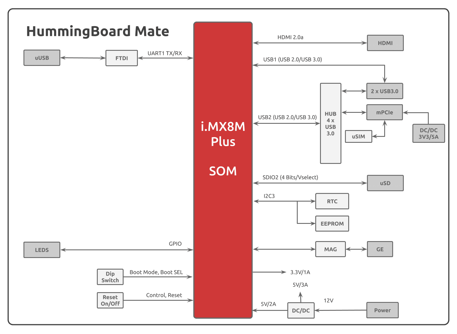
Block Diagram
The following figure describes the i.MX8M Block Diagram.
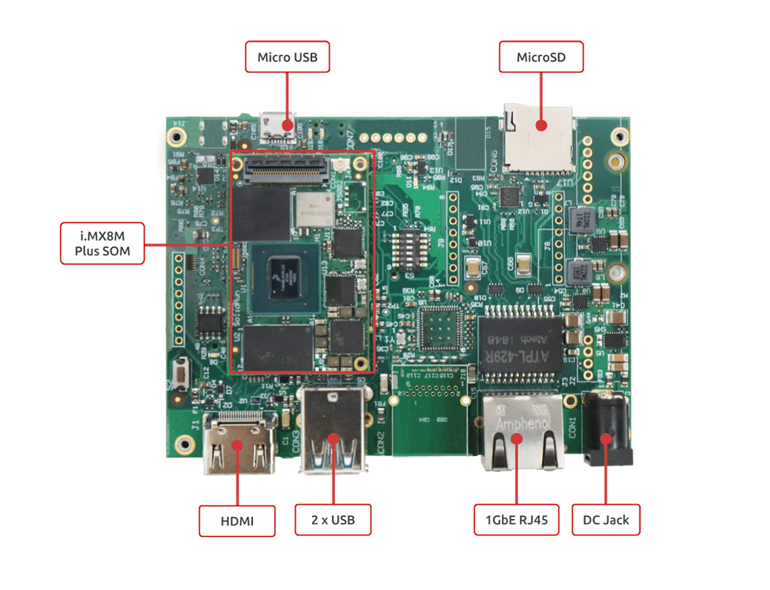
Visual features overview
Please see below the features overview of the connector side of the HummingBoard Mate.
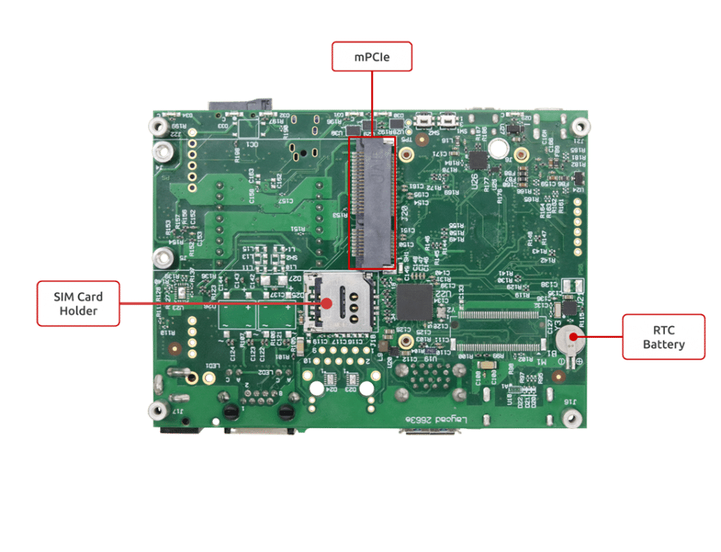
Print side connector overview of the HummingBoard Mate.
Software Setup
Cable setup and prerequisites
Here is what you will need to power up and use the board:
Linux or Windows PC
HummingBoard Mate with SOM
12V Power adapter (HummingBoard Mate has wide range input of 7V-28V).
Micro USB to USB for console, the HummingBoard Mate has an onboard FTDI chip.
IP router or IP switch
Boot Select
Before powering up the board for the first time it is recommended to select the boot media. In order to configure the boot media, please refer to HummingBoard Pulse and Ripple Boot Select .
Booting from SD card
The following shows how to set the switches on the boot source selector:
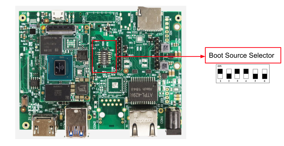
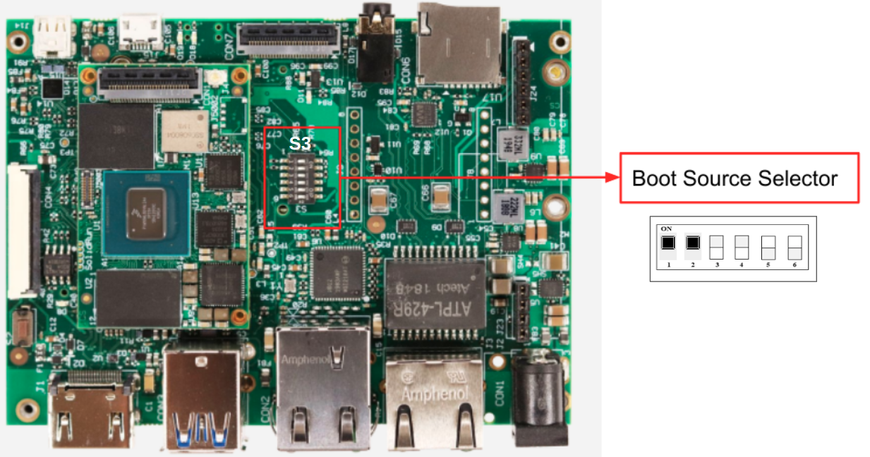
| Info |
|---|
Please Note: The black rectangle represents the switch position. |
Once you set the switches, you can apply the following for booting from SD card:
1. Downloading the Debian image
Download the Debian image by running the following command on your Linux/Windows PC:
| Code Block |
|---|
wget https://images.solid-run.com/IMX8/Debian/sr-imx8-debian-bullseye-20230623-cli-imx8mp-sdhc.img.xz |
For more Debian releases, please visit Debian Release for i.MX8.
2. Writing the image to the SD card
Use the following commands for writing the image to an SD card:
| Code Block |
|---|
xz -dc sr-imx8-debian-bullseye-20230623-cli-imx8mp-sdhc.img.xz | dd of=/dev/sdX bs=4k conv=fdatasync |
For more information, please visit Flashing an SD Card .
Note: Plug a micro SD into your Linux PC, the following assumes that the micro SD is added as /dev/sdX and all it’s partitions are unmounted.
3. SD card insertion
Please Insert the SD card into your device.
4. Power connection
Connect your power adaptor to the DC jack, and then connect the adaptor to mains supply.
5. Serial Connection
Please insert the micro USB into your device, then you can refer to Serial Connection for installing necessary serial connection software in Linux/Windows.
Once you installed the necessary serial connection software, you should be able to see the following:
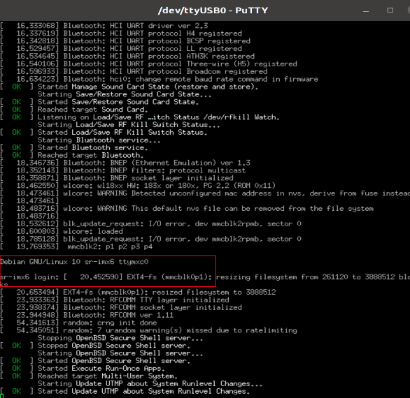
In order to be able to log in , please insert “debian” as a username and password as follows:

More Features
Internet
Connect an Ethernet cable to your HummingBoard Pulse (for internet access during boot-up).
Models HummingBoard with WiFi, can be connected via WiFi or wired Ethernet.
Please check you Ethernet connection.
Use the following commands in order to keep your system up-to-date:
| Code Block |
|---|
apt-get update apt-get upgrade reboot |
For more detailed information, please refer to i.MX8M Debian .
WiFi
You can connect to WiFi using any application, such as : connmanctl or wpa_spplicant.
An example for connecting to WiFi using wpa_supplicant:
1. To bring a WiFi interface up, run the following :
| Code Block |
|---|
ifconfig wlan0 up |
To discover your wireless network interface name, see Network Interfaces.
2. Install the wpa_supplicant package:
| Code Block |
|---|
apt-get install wpasupplicant |
3. Edit network interfaces file :
At the bottom of the file, add the following lines to allow wlan as a network connection:
| Code Block |
|---|
cat <<EOF > /etc/network/interfaces.d/wlan0 allow-hotplug wlan0 iface wlan0 inet dhcp wpa-conf /etc/wpa_supplicant/wpa_supplicant.conf iface default inet dhcp EOF |
4. Create a configuration file with the relevant ssid:
| Code Block |
|---|
cat <<EOF > /etc/wpa_supplicant/wpa_supplicant.conf
ctrl_interface=/run/wpa_supplicant
update_config=1

network={
    ssid="MYSSID"
    psk="passphrase"
}

EOF |
Check your personal ssids by running : ‘iw dev wlan0 scan’
5. Make sure it works:
Restart your device and it should connect to the wireless network. If it doesn't, repeat above steps or get help from an adult.
For more information about using wpa_supplicant , you can refer to wpa_supplicant or wpa_supplicant.
Bluetooth
1. For showing all Bluetooth devices, run the following:
| Code Block |
|---|
apt-get install bluez hciconfig -a |
2. Choose a device, and turn it on:
| Code Block |
|---|
hciconfig hci0 up |
3. Set up the Bluetooth name:
| Code Block |
|---|
hciconfig hci0 name 'SolidRun_Ble' |
4. Make your Bluetooth detectable by other devices:
| Code Block |
|---|
hciconfig hci0 piscan |
5. If you want to connect to other devices:
Start by scanning for other Bluetooth devices:
| Code Block |
|---|
hcitool scan |
Choose a MAC address and connect :
| Code Block |
|---|
rfcomm connect 0 $MAC 10 & |
You can check the communication between the devices by writing :
| Code Block |
|---|
l2ping -c 4 $MAC |
GPIO Pins Control
In order to be able to control the GPIO pins, please refer to GPIO Pins Control - HummingBoard Pulse/Mate & i.MX8M Plus SOM
Cellular Modem
The cellular modem is a more fully featured extension of which contains a cellular module with additional hardware interfaces and a SIM card slot.
You can connect your cellular modem to the mPCIe, and insert a SIM card.
For some cellular modules to be connected, please refer to Cellular Modules .
Enable the MINI-PCIe slot ‘J20’
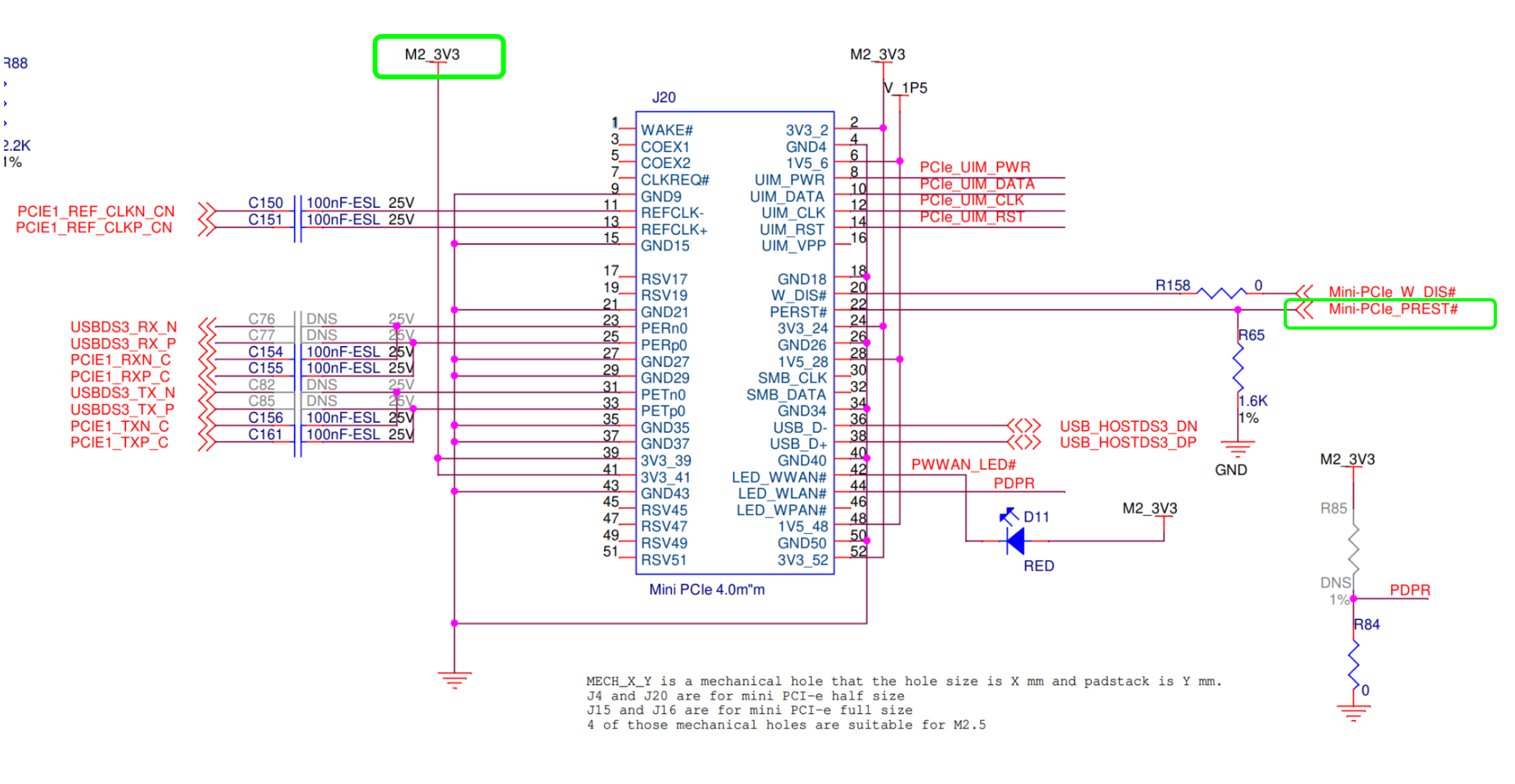
To activate the mini-pcie connector you should run the commands bellow (Enable the modem Power & do Rest):
| Code Block |
|---|
# enable power supply for M.2 and PCIe: "M2_3V3" echo 10 > /sys/class/gpio/export echo out > /sys/class/gpio/gpio10/direction echo 1 > /sys/class/gpio/gpio10/value # pcie reset: "Mini-PCIe_PREST" echo 1 > /sys/class/gpio/export echo out > /sys/class/gpio/gpio1/direction echo 1 > /sys/class/gpio/gpio1/value |
Please Note
mPCIe interface doesn't support PCIe interface - it supports USB 3.0 only.
Cellular Modem
The cellular modem is a more fully featured extension of which contains a cellular module with additional hardware interfaces and a SIM card slot.
You can connect your cellular modem to the mPCIe, and insert a SIM card.
For some cellular modules to be connected, please refer to Cellular Modules .
Enable the M.2 slot ‘M1’
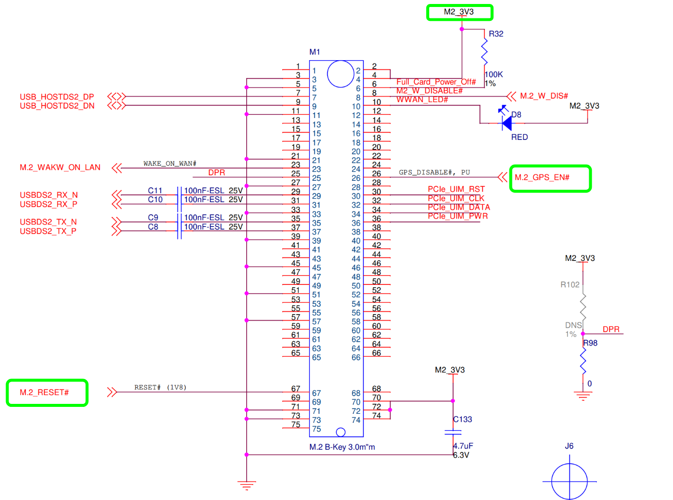
To activate the M.2 connector you should run the commands bellow (Enable the modem Power & do Rest):
| Code Block |
|---|
# enable power supply for M.2 and PCIe: "M2_3V3" echo 10 > /sys/class/gpio/export echo out > /sys/class/gpio/gpio10/direction echo 1 > /sys/class/gpio/gpio10/value # M.2 reset: "M.2_PREST" echo 6 > /sys/class/gpio/export echo out > /sys/class/gpio/gpio6/direction echo 1 > /sys/class/gpio/gpio6/value # M.2 GPS Enable: "M.2_GPS_EN" echo 7 > /sys/class/gpio/export echo out > /sys/class/gpio/gpio7/direction echo 1 > /sys/class/gpio/gpio7/value |
SPI
For testing you serial peripheral interface - SPI, please see this documentation SPI from Linux with spidev.
Basler Camera
For getting started with the Camera Module on your board, please see this documentation Basler Camera Quick Start Guide.
TLV EEPROM Support
Starting from April 01. 2022, the EEPROMs on Carriers, i.MX8M Plus SoMs are being programmed with identifying information such as the product name and SKUs to allow for programmatic identification of hardware. Check our iMXMP EEPROM documentation for additional information.
List Of Supported OS


Build from source
Documentation
| Attachments | ||||
|---|---|---|---|---|
|
| Ui button | ||||||
|---|---|---|---|---|---|---|
|
Related Articles
| Filter by label (Content by label) | ||||
|---|---|---|---|---|
|