Date
Owner
Revision
Notes
1.0
Initial release
Table of Contents
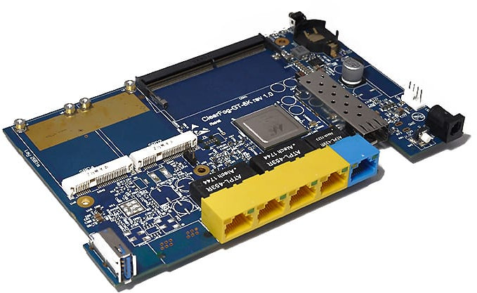
The following quick start guide provides background information about the ClearFog GT 8K.
The guide will give a technical overview about the product and by the end of it you should be able to boot an operating system and begin testing your application.
Date | Owner | Revision | Notes |
|---|---|---|---|
| 1.0 | Initial release | |
Table of Contents | |||
Processor | Marvell ARMADA A8040 quad-core Arm Cortex A72 (up to 2Ghz) |
Memory & Storage | up to 16GB DDR4 SO-DIMM |
M.2 (optional support via adapter) | |
MicroSD | |
eMMC | |
Connectivity | 4 x 1GbE switched LAN (RJ45) |
1 x 1GbE WAN (RJ45) | |
3 x mPCIe (USB 2.0 + PCIe) * | |
1 x USB 3.0 | |
1 x SFP+ (up to 10GbE) | |
I/O | GPIO header |
Indication LEDs | |
User Push Buttons | |
UART header for debug | |
OS Support | Linux Kernel 4.4x, Ubuntu 16.04, Google IoT Platform |
Power | 12V input DC jack |
Dimensions | Board: 177mm x 110mm |
Enclosed: 195 x 118 x 32mm | |
Enclosure | Optional ruggedized extruded aluminum (IP32) enclosure |
Please note (*) The default configuration in the release software:
You can change the configuration as needed |
The following figure describes the ClearFog GT 8K Block Diagram.
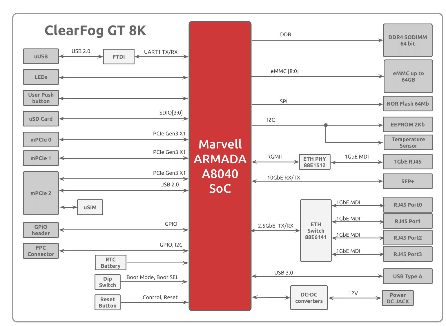
ClearFog GT 8K
SO-DIMM Memory (size depends on the order)
12V 2.5A 220/110 Power adapter EU/US version (Optional)
16GB Micro SD card (Optional)
Heatsink with a fan
Here is what you will need to power up the board:
Linux or Windows PC
ClearFog GT 8K
12V Power adapter
USB to UART cable
IP router or IP switch
Please see below the features overview of the connector side of the ClearFog GT 8K.
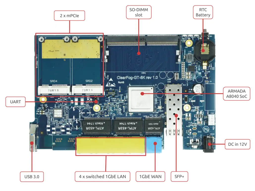
Print side connector overview of the ClearFog GT 8K.
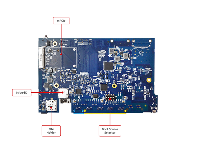
Here is what you will need to power up the board:
Linux or Windows PC
ClearFog GT 8K
Power adapter 12V@2.5A
USB to UART adapter for console
IP router or IP switch
The following is a list of industry-standard cables, sorted by type, with the necessary compliance requirements that have been proven to work well with the ClearFog product family.
These examples are the cables which SolidRun uses for testing, and should provide enough information to source products from your preferred cable vendor.
Ethernet cable: Monoprice 24AWG Cat6A 500MHz STP
USB Cable: SuperSpeed USB 3.0 Type A Male to Female Extension Cable in Black
SFP connector: GigaLite GE-GB-P1RT-E SFP module with Monoprice 24AWG Cat6A 500MHz STP cable
Before powering up the board for the first time it is recommended to select the boot media. In order to configure the boot media, please refer to ClearFog GT-8K Boot Select .
The switches on the boot source SW6 selector must be set as follows:
Switch 1 | Switch 2 | Switch 3 | Switch 4 | Switch 5 |
OFF | OFF | ON | OFF | OFF |
The following shows how to set the switches on the boot source selector:
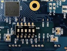
Once you set the switches, you can apply the following for booting from an SD card.
Please Note: Boot is made from SPI by default |
1. Downloading the Debian image
Download the Debian image by running the following command on your Linux/Windows PC:
wget https://solid-run-images.sos-de-fra-1.exo.io/8040/Debian/sr-8040-debian-buster-20190616-cfgt-sdhc.img.xz |
For more Debian releases, Download a pre-built snapshot image from SolidRun Images
2. Writing the image to the SD card
Use the following commands for writing the image to an SD card:
xz -dc sr-8040-debian-buster-20190616-cfgt-sdhc.img.xz | dd of=/dev/sdX bs=4k conv=fdatasync |
For more information, please visit Flashing an SD Card .
Note: Plug a micro SD into your Linux PC, the following assumes that the micro SD is added as /dev/sdX and all it’s partitions are unmounted.
Note: Plug a micro SD into your Linux PC, the following assumes that the micro SD is added as /dev/sdX and all it’s partitions are unmounted.
3. SD card insertion
Please Insert the SD card into your device.
4. Power connection
Connect your power adaptor to the DC jack, and then connect the adaptor to mains supply.
5. Serial Connection
Please insert the micro USB into your device, then you can refer to Serial Connection for installing necessary serial connection software in Linux/Windows.
On the top side of the ClearFog GT 8K, there is a header for connecting the adapter cable (J27). The cable should be connected as seen at the picture below:

Please Note The pin that is closest to the mechanical hole should be connected to the ground cable (black), the middle pin should be connected to the Tx (green cable) and the 3’rd pin should be connected to the Rx (white). The red cable should not be connected! |
Once you installed the necessary serial connection software, you should be able to see the following:
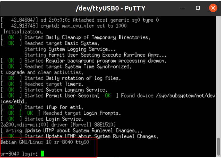
In order to be able to log in, please insert “debian” as a username and password as follows:

Connect an Ethernet cable to your HummingBoard Pulse (for internet access during boot-up).
Please check your Ethernet connection.
Use the following commands in order to keep your system up-to-date:
apt-get update apt-get upgrade reboot |
You can build your own image using the script in here – GitHub - SolidRun/clearfog-gt-8k-build
U-Boot - GitHub - SolidRun/8040-uboot
