Revision and Notes
Date | Owner | Revision | Notes | ||||||
|---|---|---|---|---|---|---|---|---|---|
| 1.0 | Initial release | |||||||
Table of Contents |
| ||||||||
Introduction
The following quick start guide provides background information about the ClearFog Pro product which use the A388 System on module.
The guide will give a technical overview about the product and by the end of it you should be able to boot an operating system and begin testing your application.
Specifications
SOM Model | ARMADA based A388 | ||||||||
Processor | 32-bit Cortex A9 | ||||||||
Core Frequency | up to 1.6GHz | ||||||||
Memory & Storage | 32bit DDR3 W/ ECC, Up to 2GB at 1600MT/s | ||||||||
M.2 | |||||||||
uSD or 8GB eMMC (Optional) | |||||||||
Connectivity | 2 x mSATA/mPCIE | ||||||||
1 x USB 3.0 port | |||||||||
1 x Port dedicated Ethernet | |||||||||
5 x Port switched Ethernet | |||||||||
1 x SFP 2.5GbE | |||||||||
I/O & Misc. | Analog Audio/TDM module support | ||||||||
GPIO Header (mikroBUS) | |||||||||
Indication LEDs | |||||||||
User Push Buttons | |||||||||
PoE expansion header | |||||||||
RTC Battery | |||||||||
FTDI (Console Only)/Debug Header | |||||||||
JTAG Header | |||||||||
OS Support | Linux Kernel 4.x, OpenWRT/LEDE, Yocto | ||||||||
Power | Wide range 9V- 32V | ||||||||
Advanced Power Control | |||||||||
Fan Control | |||||||||
Dimensions | 225mm x 100mm (PCBA) | ||||||||
226mm x 104mm x 33mm (Enclosed) | |||||||||
Enclosure | Optional metal enclosure | ||||||||
|
| Info |
|---|
Supported with A388 SOM. For more detailed information about our A388 SOM series please visit this user manual : A388 SOM Hardware User Manual . |
Block Diagram
The following figure describes the ClearFog Pro Block Diagram.
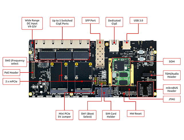
Visual features overview
Please see below the features overview of the connector side of the ClearFog Pro (A388 SOM assembled).
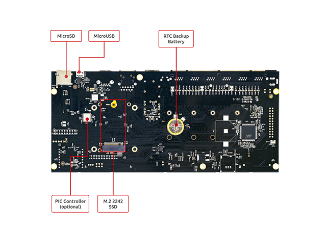
Print side connector overview of the ClearFog Pro.
Software Setup
Cable setup and prerequisites
Here is what you will need to power up the board:
Linux or Windows PC
ClearFog Pro with SOM
12V Power adapter (ClearFog Pro has wide range input of 9V-32V, it is recommended to use 12V power adapter)
Micro USB to USB for console, the ClearFog Pro has an onboard FTDI chip.
IP router or IP switch
Recommended Cables
The following is a list of industry-standard cables, sorted by type, with the necessary compliance requirements that have been proven to work well with the ClearFog product family (ClearFog Base / Pro).
These examples are the cables which SolidRun uses for testing, and should provide enough information to source products from your preferred cable vendor.
Ethernet cable: Monoprice 24AWG Cat6A 500MHz STP
USB Cable: SuperSpeed USB 3.0 Type A Male to Female Extension Cable in Black
SFP connector: GigaLite GE-GB-P1RT-E SFP module with Monoprice 24AWG Cat6A 500MHz STP cable
Boot Select
Before powering up the board for the first time it is recommended to select the boot media. In order to configure the boot media, please refer to ClearFog A388 Boot Select .
Booting from an SD card
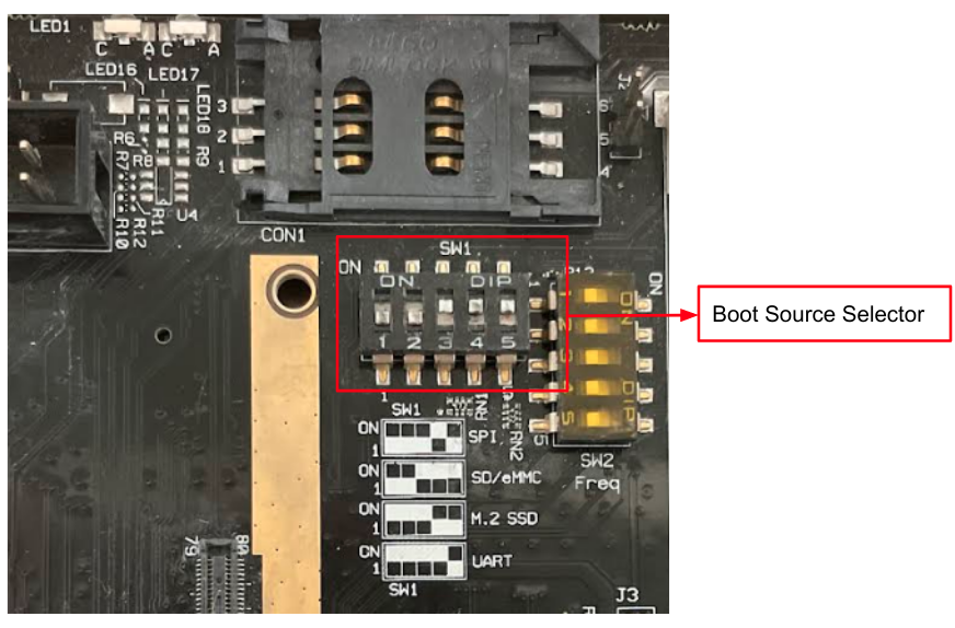
The switches on the boot source selector must be set as follows:
Switch 1 | Switch 2 | Switch 3 | Switch 4 | Switch 5 |
OFF | OFF | ON | ON | ON |
The following shows how to set the switches on the boot source selector:
Once you set the switches, you can apply the following for booting from an SD card.
1. Downloading the Debian image
| Code Block |
|---|
wget https://solid-run-images.sos-de-fra-1.exo.io/A38X/Debian/sr-a38x-debian-buster-20200114.img.xz |
For more Debian releases, please visit Debian Releases for Armada 38X.
2. Writing the image to the SD card
Use the following commands for writing the image to an SD card:
| Code Block |
|---|
xz -dc sr-a38x-debian-buster-20200114.img.xz | dd of=/dev/sdX bs=4k conv=fdatasync |
For more information, please visit Flashing an SD Card .
Note: Plug a micro SD into your Linux PC, the following assumes that the micro SD is added as /dev/sdX and all it’s partitions are unmounted.
3. U-Boot installation
| Code Block |
|---|
wget https://solid-run-images.sos-de-fra-1.exo.io/A38X/U-Boot/u-boot-clearfog-pro-sdhc.kwb |
4. Writing U-Boot to the SD card
| Code Block |
|---|
dd if=u-boot-clearfog-pro-sdhc.kwb of=/dev/sdX bs=512 seek=1 conv=sync status=progress |
For more information, you can refer to A38X A38x U-Boot .
5. SD card insertion
Please Insert the SD card into your device.
6. Power connection
Connect your power adaptor to the DC jack, and then connect the adaptor to mains supply.
7. Serial Connection
Please insert the micro USB into your device, then you can refer to Serial Connection for installing necessary serial connection software in Linux/Windows.
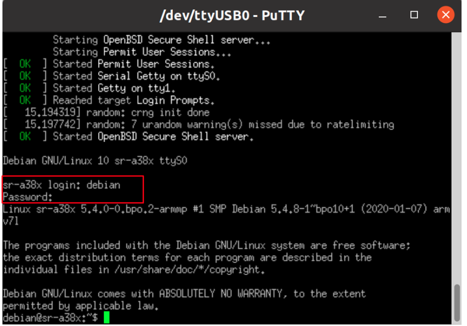
Once you installed the necessary serial connection software, you should be able to see the following:
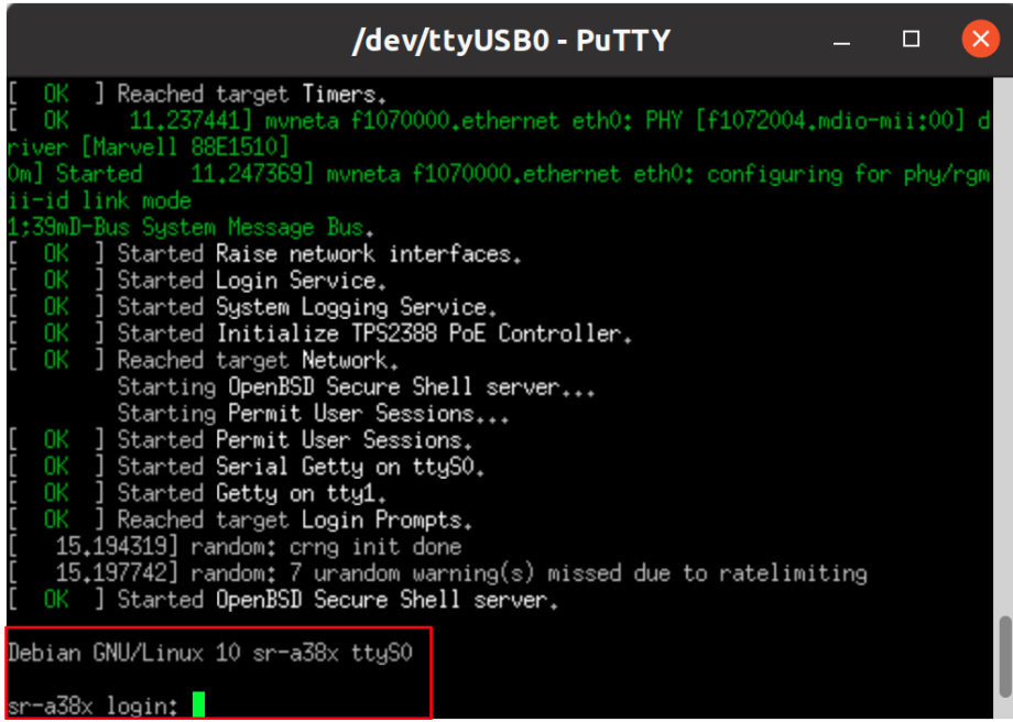
In order to be able to log in , please insert “debian” as a username and password as follows:
GPIO pins Control
To control on the GPIO pins, please follow this page ClearFog Base/Pro GPIO Pins Control .
SFP Modules
For some SFP modules that work on SolidRun networking hardware platforms, please refer to SFP Modules .
SIM Card Slot
It is possible to utilize a Cellular connection by inserting a SIM card into the SIM card slot. Please observe that a GSM Cellular modem needs to be installed utilizing the mini PCIe connection in order to exploit the cellular connection.
| Note |
|---|
Please Note If you your ClearFog has dual SIM card slots, an additional cellular modem will need to be installed in the mini PCIe connection in order to utilize the 2nd SIM connection. |
List Of Supported OS


Build U-Boot & kernel from sources
U-Boot Build - A38X U-Boot
Kernel Build - A388 Kernel
Documentation
| Attachments | ||||
|---|---|---|---|---|
|
| Ui button | ||||||
|---|---|---|---|---|---|---|
|
Related Articles
| Filter by label (Content by label) | ||||
|---|---|---|---|---|
|